Calculating the moment of inertia of an Aluminum I Beam is a crucial step in various engineering and construction applications. As a leading supplier of Aluminum I Beams, I understand the significance of this calculation in ensuring the structural integrity and performance of your projects. In this blog post, I will guide you through the process of calculating the moment of inertia of an Aluminum I Beam, explain its importance, and provide practical examples to help you apply this knowledge effectively.
Understanding the Moment of Inertia
The moment of inertia, also known as the second moment of area, is a measure of an object's resistance to changes in its rotational motion. In the context of an Aluminum I Beam, it quantifies the beam's ability to resist bending under a load. A higher moment of inertia indicates greater resistance to bending, making the beam more suitable for applications where structural stability is critical.
The moment of inertia is denoted by the symbol (I) and is calculated differently depending on the axis of rotation. For an Aluminum I Beam, we are typically interested in two primary axes: the x-axis (horizontal axis passing through the centroid of the beam) and the y-axis (vertical axis passing through the centroid of the beam).
Calculating the Moment of Inertia of an Aluminum I Beam
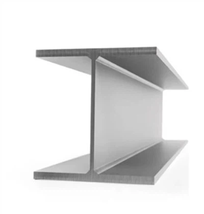
To calculate the moment of inertia of an Aluminum I Beam, we need to know its cross-sectional dimensions. An Aluminum I Beam typically consists of a web (the vertical part of the beam) and two flanges (the horizontal parts of the beam). The following steps outline the process of calculating the moment of inertia about the x-axis ((I_x)) and the y-axis ((I_y)):
Step 1: Determine the Cross-Sectional Dimensions
Measure the width of the flanges ((b)), the thickness of the flanges ((t_f)), the height of the web ((h)), and the thickness of the web ((t_w)) of the Aluminum I Beam. These dimensions are essential for calculating the moment of inertia.
Step 2: Calculate the Moment of Inertia about the x-axis ((I_x))
The moment of inertia about the x-axis can be calculated using the following formula:
[I_x=\frac{1}{12}b h^3-\frac{1}{12}(b - t_w)(h - 2t_f)^3]
where:
- (b) is the width of the flanges
- (h) is the total height of the beam
- (t_w) is the thickness of the web
- (t_f) is the thickness of the flanges
Step 3: Calculate the Moment of Inertia about the y-axis ((I_y))
The moment of inertia about the y-axis can be calculated using the following formula:
[I_y = 2\times\frac{1}{12}t_f b^3+\frac{1}{12}t_w h^3]
where the first term represents the contribution of the two flanges and the second term represents the contribution of the web.
Practical Example
Let's consider an Aluminum I Beam with the following dimensions:
- Width of the flanges ((b)) = 100 mm
- Thickness of the flanges ((t_f)) = 10 mm
- Height of the web ((h)) = 200 mm
- Thickness of the web ((t_w)) = 8 mm
Calculate (I_x)
[
\begin{align*}
I_x&=\frac{1}{12}\times100\times200^3-\frac{1}{12}(100 - 8)(200 - 2\times10)^3\
&=\frac{1}{12}\times100\times8\times10^6-\frac{1}{12}\times92\times180^3\
&=\frac{8\times10^8}{12}-\frac{92\times5.832\times10^6}{12}\
&=\frac{8\times10^8 - 92\times5.832\times10^6}{12}\
&=\frac{800\times10^6- 536.544\times10^6}{12}\
&=\frac{263.456\times10^6}{12}\
&= 21.9547\times10^6\space mm^4
\end{align*}
]
Calculate (I_y)
[
\begin{align*}
I_y&=2\times\frac{1}{12}\times10\times100^3+\frac{1}{12}\times8\times200^3\
&=\frac{2\times10\times10^6}{12}+\frac{8\times8\times10^6}{12}\
&=\frac{20\times10^6+64\times10^6}{12}\
&=\frac{84\times10^6}{12}\
&=7\times10^6\space mm^4
\end{align*}
]


Importance of Calculating the Moment of Inertia
Calculating the moment of inertia of an Aluminum I Beam is essential for several reasons:
- Structural Design: Engineers use the moment of inertia to design structures that can withstand the expected loads without excessive bending or deformation. By selecting an Aluminum I Beam with an appropriate moment of inertia, they can ensure the safety and durability of the structure.
- Material Selection: The moment of inertia helps in comparing different Aluminum I Beam profiles and selecting the most suitable one for a specific application. Beams with higher moments of inertia are generally more suitable for applications where high strength and stiffness are required.
- Cost Optimization: By accurately calculating the moment of inertia, engineers can optimize the design of the structure and select the most cost-effective Aluminum I Beam. This helps in reducing material waste and overall project costs.
Our Aluminum I Beam Products
As a trusted Aluminum I Beam supplier, we offer a wide range of high-quality Aluminum I Beam products to meet your specific requirements. Our Aluminum I Beams are available in various sizes and specifications, and we also offer Anodized Aluminum I Beam for enhanced corrosion resistance. Additionally, we also supply Carbon Steel I Steel for applications where different material properties are needed.
Our team of experts can assist you in selecting the right Aluminum I Beam for your project and provide you with the necessary technical support. Whether you are working on a small-scale construction project or a large industrial application, we have the expertise and resources to meet your needs.
Contact Us for Procurement
If you are interested in purchasing Aluminum I Beams for your project, we invite you to contact us for procurement discussions. Our sales team will be happy to provide you with detailed product information, pricing, and delivery options. We are committed to providing our customers with the highest level of service and support, and we look forward to working with you on your next project.
References
- Gere, J. M., & Goodno, B. J. (2012). Mechanics of Materials. Cengage Learning.
- Timoshenko, S. P., & Gere, J. M. (1972). Theory of Elastic Stability. McGraw-Hill.